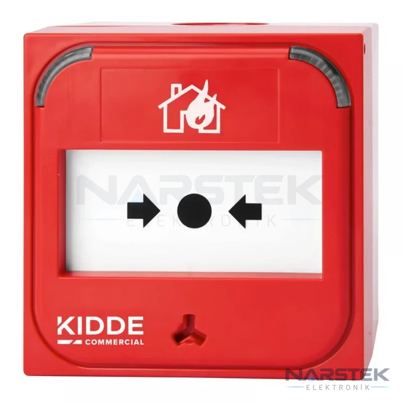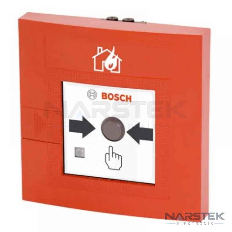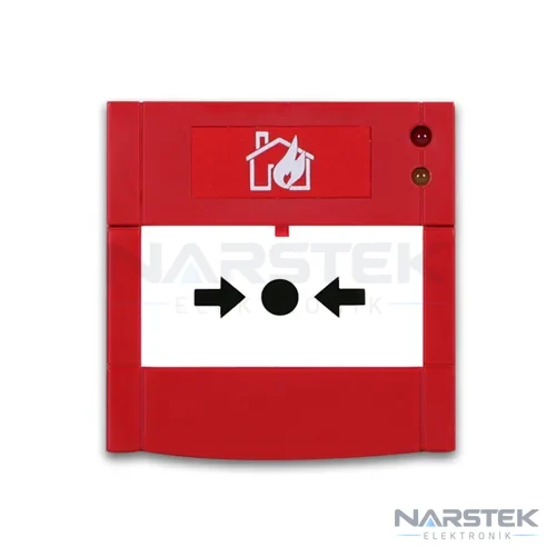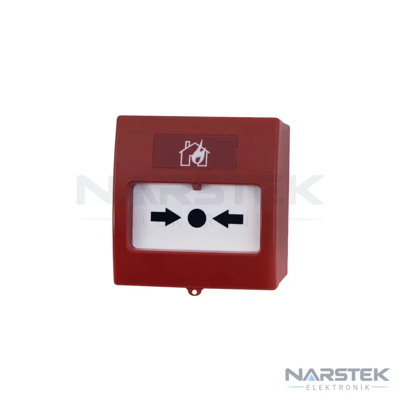
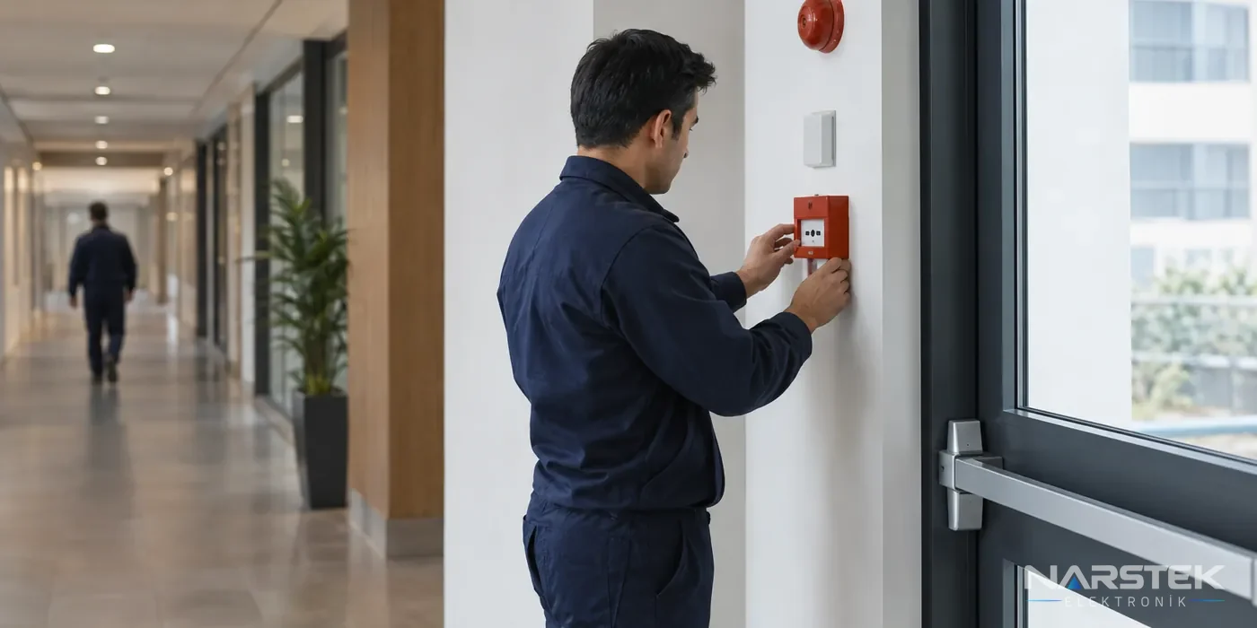
Manual call points are installed near escape routes and exits, where they are easy to notice and reach. A common site practice for manual call point mounting height is to position the operating element approximately 1.2–1.4 m above the finished floor.
This range alone is not sufficient to determine the mounting position. The layout in the design should be assessed alongside TS CEN/TS 54-14 and the device manufacturer’s installation instructions. The position of sounders and beacons is also determined by the building’s use, ambient noise and the coverage characteristics of the devices.
Where should a manual call point be installed?
A manual call point should be positioned so that anyone in the building can raise the alarm without delay and can see it easily while escaping. Stairwell exits, the ends of corridors along escape routes and areas near exit doors should be considered in the layout plan. Placing a manual call point behind a door, inside a cupboard or behind temporarily stored items can make it difficult to use.
In buildings with multiple exits or long corridors, installing a manual call point only at the main entrance may not be sufficient. All escape routes should be reviewed as part of the design, and the position of manual call points should be determined in relation to the routes taken by building users. The layout should also be checked for partitions that obstruct visibility, door swing direction and furniture that could restrict access.
There should be no other equipment around the manual call point that could make it difficult to identify or use. After installation, check that the device is correctly detected by the fire panel and that the required alarm sequence operates. A site survey, design, installation and maintenance for Fire Detection and Alarm Systems can be planned to suit the building’s conditions.
How is the mounting height of a manual call point selected?
A mounting height of approximately 1.2–1.4 m is common practice for manual call points. The measurement should be taken at the operating element used to raise the alarm, not at the top edge of the device enclosure. If the installation design or manufacturer’s instructions specify a different value, install the device accordingly.
Measure from the finished floor level. Wall finishes, skirting boards or later alterations can affect the measurement, so the mounting height should be determined in relation to the completed floor level. In areas used by children or people with reduced mobility, accessibility should also be assessed with the design team.
If a manual call point in an existing building needs to be repositioned, moved to another location or supplemented with an additional one, simply making space on the wall is not sufficient. The cabling, system type and zone or address information at the panel must also be checked. In an addressable system, each device is shown at the panel under its own address; in a conventional system, devices are monitored by zone. Addressable device compatibility depends on the panel protocol, and it should not be assumed that devices from different manufacturers will work together.
| Check point | What to consider during installation |
|---|---|
| Location | Choose a visible and accessible position near escape routes and exits. |
| Height | Assess the operating element at the commonly used 1.2–1.4 m range; verify the design and manufacturer’s instructions. |
| After installation | Check that the manual call point is correctly detected by the panel and that it activates the alarm sequence. |
How should sounders and beacons be positioned?
The aim when positioning sounders is to ensure that the alarm can be heard in the areas in use. Corridors, rooms, communal areas and work areas may have different acoustic conditions. Therefore, the number and position of sounders should not be determined simply by spacing devices evenly across the ceiling; the building layout, closed doors and ambient noise must also be considered.
In areas such as plant rooms, production areas or spaces with high levels of background noise, the audibility of the audible warning should be assessed separately. In such areas, relying only on a sounder in the main corridor may not be appropriate. The design should consider the positioning of audible warnings and the use of visual warnings where necessary. Audible fire warning devices are among the products covered by EN 54-3, and visual warning devices by EN 54-23.
The light from a beacon should be visible from the area occupied by users. Check on site whether columns, shelving, partitions or decorative features obscure the device. Compliance of a visual warning device with the relevant standard does not, by itself, mean that it will be visible from every point; positioning and lines of sight should also be assessed as part of the design.
If there is any uncertainty about alarm audibility or beacon visibility, the building’s use and the locations of existing devices should be assessed together. Product selection in the Sounders and Beacons category should be compatible with the panel and system configuration. Do not assume a particular sound pressure level or coverage value from a sounder’s catalogue without checking the product documentation.
What checks should be carried out before and after installation?
Before installation, confirm the device type, position and surrounding conditions of use. Verify from the design that the manual call point is addressable or conventional, that it is compatible with the existing panel and that the wiring connections are correct. For outdoor or special-use areas, check the manufacturer’s documentation to confirm that the selected device is suitable for those conditions.
- Check that the manual call point is visible and accessible on the escape route.
- Measure the height of the operating element from the finished floor.
- Assess the area served by the sounder and any potential sources of noise.
- Check whether any shelving, partitions or equipment obstruct the beacon’s visibility.
- After installation, test that the device is correctly recognised by the control panel and that the relevant warning operates.
A practical issue encountered during maintenance visits is that a device may be blocked or become harder to access during refurbishment. A new partition wall, tall cabinet or change to the working layout can affect the visibility of a call point that was correctly positioned before. Device locations should be checked again after changes are made inside the building.
To understand the overall structure of the existing system, you can also read the article on the difference between addressable and conventional fire alarms. For information about the system design and commissioning process, see the article on the stages of fire alarm system installation.
Example call points from the catalogue
When selecting a call point model, consider the system type and where it will be used. The examples below show different product groups; this does not mean that any one model is suitable for every panel or environment.
- The Aritech KE-DM3010R-KIT Addressable Manual Call Point is an addressable model designed for surface mounting.
- The Bosch FMC-210-DM-G-R Double-Action Manual Call Point is listed as a double-action call point.
- The Teknim TFB-3165 Conventional Manual Call Point is a resettable model suitable for flush or surface mounting.
- The Mavili ML-1710 Intelligent Addressable Manual Call Point is an addressable product with flush or surface mounting options.
The product features in these examples are limited to the information provided. For sounder and beacon selection, the model’s datasheet and compatibility with the panel should also be checked. You can find all call point options in the Call Points category.
Arrange a site survey and quote with Narstek
Narstek Elektronik, based in Istanbul, provides site surveys, design, installation, maintenance and fault repair for fire detection and alarm systems, as well as projects and product supply across Türkiye. To start an assessment of the system layout, share the building’s use, floor plans, the make and model of the existing panel, call point and sounder locations, and any refurbishment information, if available.
You can submit a request for a quote or site survey using the site survey / quote form, call 0212 424 07 24, or message us on WhatsApp at 0540 001 07 24. Photos of the existing devices and an up-to-date floor plan, if available, will help with the layout and compatibility assessment.
Frequently asked questions
What height should a fire call point be mounted at?
Common practice is to position the operating element of the call point approximately 1,2–1,4 m above the finished floor. The exact value should be checked against the project, TS CEN/TS 54-14 and the manufacturer’s instructions.
Should a fire call point only be installed next to the main exit?
Buttons are installed near escape routes and exits, where they are visible and accessible. If the building has more than one escape route, their positioning should be designed with all routes in mind.
Is a siren on its own sufficient in noisy areas?
This depends on the ambient noise level and device positioning; decisions should not be based on numerical assumptions. The audibility of the audible warning is assessed as part of the design, and beacons are also planned for areas where they are considered necessary.
Can an addressable manual call point be connected to an existing panel?
The compatibility of addressable devices depends on the panel’s communication protocol. Do not connect devices until compatibility with the make and model has been verified against the product and panel documentation.
Share the panel brand, number of devices and address, and we’ll get back to you about a site survey and quote.