
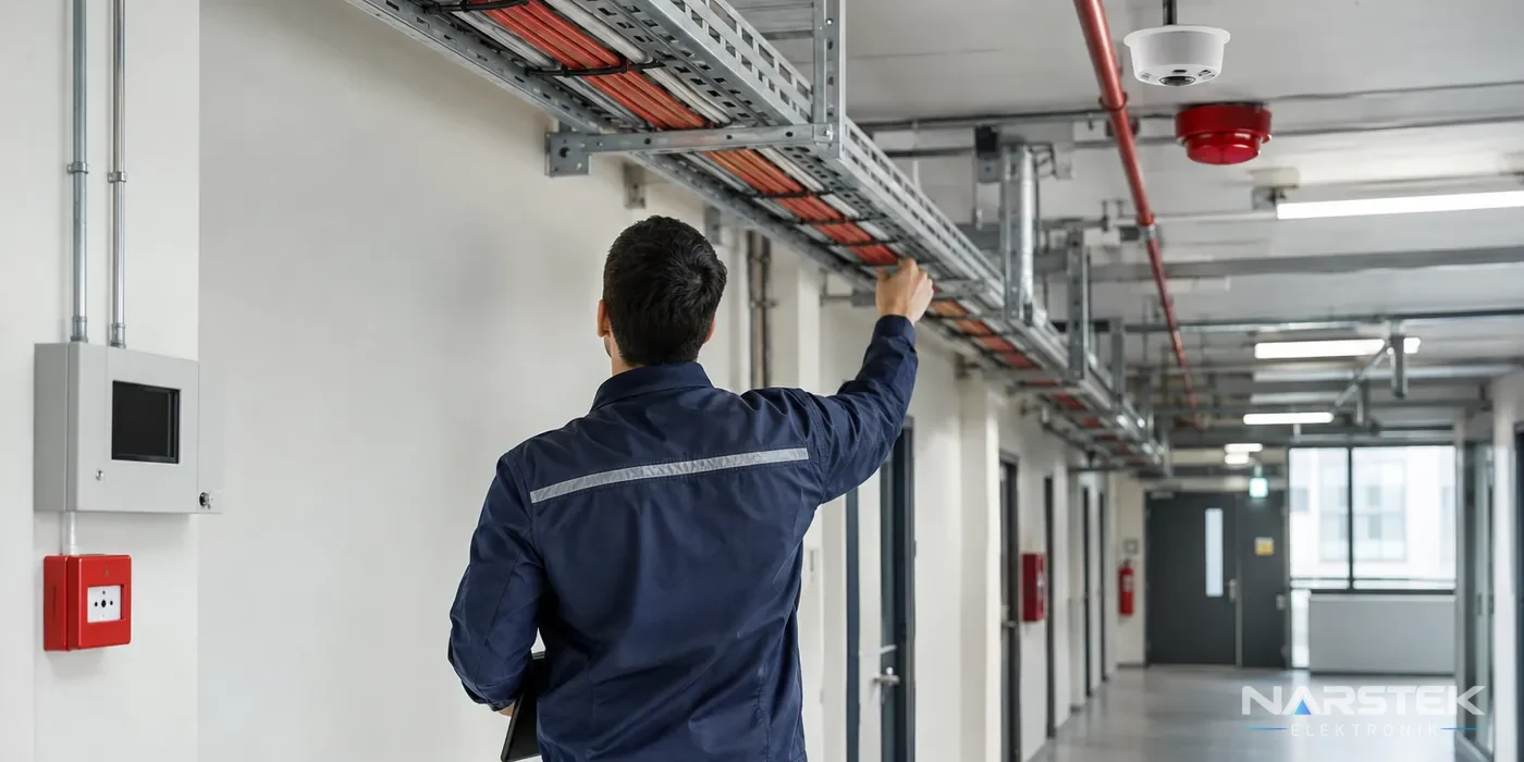
When selecting fire alarm cable, do not consider only the number of cores or the cable’s appearance. Assess the fire-resistance class required by the project, halogen-free construction, circuit type and cable cross-section together.
The wrong cable can lead to circuit faults at the panel, communication problems or loss of circuit function during a fire. Make the selection based on the panel manufacturer’s documentation and the approved project.
How should the fire-resistant cable class be assessed
Fire-resistant cable specified in the project must be used for fire alarm circuits. Markings such as FE180 and PH120 are among those you may encounter when selecting cable. However, do not treat these codes as interchangeable indicators of a single characteristic. Compare the class specified in the project with the definition in the cable datasheet and the manufacturer’s application guidance.
The presence of a class marking on a cable does not mean it is suitable for every application. The type of circuit, the route it follows and the system manufacturer’s connection requirements must also be checked. If the class specified in the project does not match the product documentation, seek clarification from the project lead or system manufacturer before installation.
Fire detection and alarm system design should be considered alongside cable selection. For information about the overall system, visit our Fire Detection and Alarm Systems services page.
What does halogen-free, low-smoke cable provide
Halogen-free, low-smoke cables are designed to produce less smoke and fewer harmful gases during a fire than cables containing halogens. This characteristic is assessed against project requirements, particularly in areas used by occupants, such as escape routes and communal areas. Do not consider the term “halogen-free” sufficient on its own; verify the fire-resistance class separately.
Read the markings on the cable sheath and check the specifications in the datasheet. If the supplied product’s compliance with the project requirements needs to be documented, file the technical documentation together with the product label. Cables with different characteristics may be routed alongside one another on the same tray; in that case, clearly identify which system each circuit belongs to during installation.
Is shielded cable required for every circuit
Shielded cable may be used to reduce interference that external electrical influences can cause on communication or signal circuits. However, it cannot be said that shielded cable is required for every fire alarm circuit. The cable type should be determined in accordance with the panel and connected devices’ manufacturer documentation, the project requirements and the circuit route.
When shielded cable is selected, the way the screen is terminated is also important. The screen must be connected in accordance with the system design and must not be earthed at multiple points arbitrarily. The installation team should follow the connection instructions in the panel and device documentation. Incorrectly terminating shielded cable, even when it has been selected correctly, can also cause communication problems.
Cable cross-section, voltage drop and loop length
Cable cross-section is selected by considering the circuit length and the electrical requirements of the connected devices together. As the distance increases, the effect of circuit resistance may become greater, which can affect the voltage at the far end. The current, cable characteristics, number of devices and acceptable voltage range used in the calculation should be taken from the panel and device manufacturers’ documentation. It is not good practice to select a cable by referring to a “standard cross-section” alone, without these details.
In addressable systems, a loop is a ring circuit fed from both ends. Devices on the loop communicate with the panel; isolators help protect the remaining part of the circuit in the event of a short circuit. Do not use a single, universal value for loop length. The permitted total length depends on the panel, cable type and cross-section, number of devices and system manufacturer’s limits.
In conventional systems, devices are monitored by zone rather than having individual addresses at the panel. In addressable systems, each device has its own address at the panel. Addressable detectors and modules must be compatible with the panel protocol; devices from different brands often may not work together. For more information about system types and panel compatibility, see our article on the difference between addressable and conventional fire alarm systems.
If the cross-section or loop length needs to be changed on site, compare the change with the project requirements and manufacturer limits before commissioning. Extending the cable route, adding devices or routing the circuit along a different path can affect the calculations. For this reason, record subsequent modifications in the project documentation and verify the circuit during system testing.
Cable tray and clamp selection
As well as ensuring the cable is suitable, it is important to use a support system that keeps it in place along the route. Fire-resistant cable must not be fixed indiscriminately to a tray or clamp intended for ordinary cable. Check that the cable and support system are suitable for use together under fire conditions, in accordance with the project requirements and manufacturer documentation.
- Plan fire alarm cable routes separately from other services, and label the circuits.
- Avoid fixings that could crush the cable, damage its outer sheath or create sharp bends.
- When selecting cable trays and clamps, verify that they meet the requirements of the cable type and application.
- Arrange joints and connection points so they remain accessible and can be inspected.
Applying a single fixing interval to every project is not appropriate. The interval and installation method should be determined based on the supporting system manufacturer’s information and the project conditions. Securing the cable with clamps that are unsuitable for the tray may prevent the circuit from operating as expected during a fire.
Common mistakes when using standard cables
One issue encountered during maintenance and fault investigations is the use of general-purpose cable on a fire alarm circuit where the project specification calls for fire-resistant cable. Another mistake is checking only that the number of cores is correct, without verifying the cable’s fire resistance, halogen-free properties or screening requirements.
- Increasing the loop length or device count without checking the manufacturer’s limits.
- Selecting the required conductor cross-section without calculating voltage drop.
- Using addressable devices that are incompatible with the panel protocol on the same circuit.
- Terminating the screen contrary to the manufacturer’s instructions.
- Securing fire-resistant cable with trays and clamps whose suitability has not been verified.
- Failing to record the cable route and any changes made after alterations.
These errors may be noticed during commissioning or may later appear as open-circuit, short-circuit or communication faults. During periodic inspections, panel warnings and field connections should be assessed together. For the inspection process, see our fire alarm system maintenance checklist.
Request a Site Survey and Cable Selection Support from Narstek
Narstek Elektronik, based in Istanbul, provides site surveys, design, installation, maintenance and fault repair services for fire detection and alarm systems. We also support projects and product supply across Türkiye. If you would like an assessment for cable selection or a fault on an existing circuit, please share whether the system is addressable or conventional, along with any project or panel information you have.
When requesting a quote, provide the building’s use, approximate area, number of floors, existing panel model, device count, estimated cable routes and, if available, the cable datasheet. For a new installation, include the project documentation; for an existing system, include the panel fault records and details of any alterations to help us assess your requirements more accurately. You can complete the Request a Survey / Quote form or submit a technical service request.
For information by phone, call 0212 424 07 24. You can send us your project details and, if available, a photo of the cable label via WhatsApp at 0540 001 07 24. Narstek Elektronik's address is Tevfikbey Mah. Halkalı Cad. No:112 Nazlı İş Merkezi Kat:3 Ofis No:64 Küçükçekmece / İstanbul.
Frequently asked questions
Do FE180 and PH120 refer to the same cable characteristic?
Do not use these markings interchangeably. Check the class specified in the project alongside the description in the cable datasheet, and verify suitability against the project requirements.
Is shielded cable compulsory for fire alarm cables?
It cannot be said that shielded cable is required for every circuit. Consider the connection documentation from the panel and device manufacturers, the project requirements and the circuit route.
Is there a fixed limit for the length of a loop circuit?
There is no single length that applies to all systems. The panel, cable cross-section and type, number of devices, and manufacturer limits must all be considered.
What information is needed before replacing cables in an existing building?
The panel model, whether the system is addressable or conventional, the existing project documentation and the cable route are useful starting points. If available, also share fault logs and the datasheet for the cable in use.
Share the panel brand, number of devices and address, and we’ll get back to you about a site survey and quote.