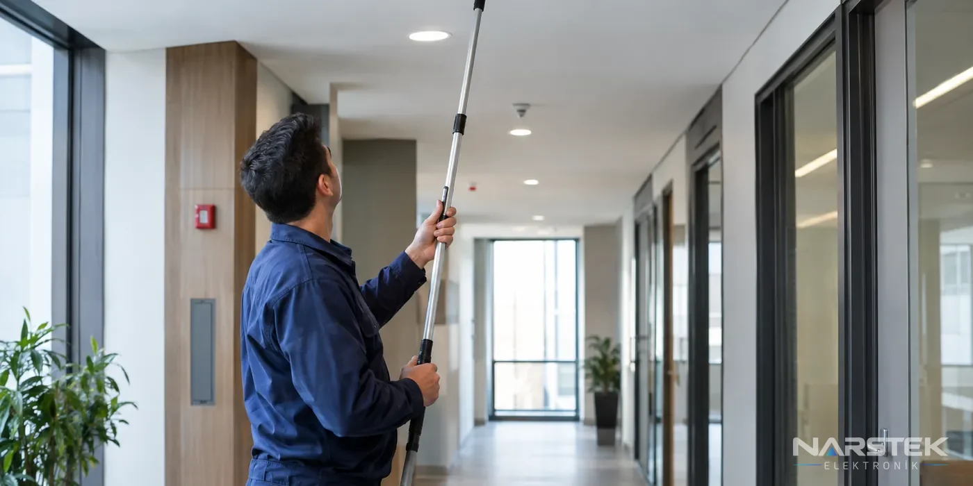
Addressable fire alarm maintenance involves matching the devices shown on the panel with the project documentation, testing the loop and detectors, and verifying the alarm sequences. At the end of the maintenance visit, the system status, tests carried out and faults requiring attention should be provided in a written report.
In addressable systems, each detector and module is monitored by the panel at a separate address. Maintenance therefore involves more than simply checking whether the panel has a fault light. It also verifies that each device appears at the correct address and location, and that the relevant sequence operates when it raises an alarm.
The project documentation and panel list are compared before maintenance
As a first step, the device list recorded in the panel is compared with the device locations in the approved project documentation. The address, device type and location of detectors, manual call points and input/output modules are checked. Site alterations, relocated partitions or replaced devices can create discrepancies between the project documentation and the panel.
If a device appears on the panel under the name of a different location, it may take longer to identify the source of an alarm. This is also where addressable systems differ from conventional systems: in a conventional system, an alarm is generally traced to a zone, whereas an addressable system identifies an individual device address on the panel. Any replacement device must be compatible with the panel protocol; products from different brands are often not directly compatible.
The maintenance team should verify the device list against the site and record any devices that appear to be missing or additional. Any device not configured in the panel, incorrect address, incorrect location name, or element shown in the project documentation but not in the panel should be clearly recorded in the report. If current project documentation or a device list is unavailable, this should also be noted.
How are the panel, analogue values and event log checked?
Check the panel for active faults, disabled devices, earth leakage or communication faults. Depending on their measurement and monitoring capabilities, addressable panels can display devices’ analogue values and contamination status. Interpret these values in accordance with the manufacturer’s limits and the panel’s protocol; a single figure should not be treated as applicable to all detectors.
A detector showing a contamination warning should not be treated as a notification that can simply be silenced at the panel. Assess the detector’s environment, any visible dust or dirt, its installation and the manufacturer’s maintenance procedure. Clean the detector in a way that is suitable for its design, and avoid arbitrary interventions that could affect its sensitivity.
The event log is an important reference during maintenance. Review the latest alarm, fault, reset and disablement records to identify recurring events or warnings concentrated on a particular device. Note the records before maintenance, and distinguish between events generated during testing, work carried out and the time the panel returned to normal in the report.
Loop continuity and isolator test
A loop is an addressable circuit that leaves the panel, forms a circuit and returns to the panel. During maintenance, check that the panel correctly identifies the devices on the loop and that there are no communication or continuity problems on the line. Also inspect accessible connection points, boxes and cable routes for damage, loose connections or unsuitable joints.
Short-circuit isolators are used to limit the effect of a short circuit on the rest of the loop. Check the isolator’s location and the fault indication on the panel. Plan operational testing in accordance with the system manufacturer’s procedure, taking into account that fire protection may be temporarily affected. Inform the building representatives before testing, and confirm afterwards that isolated sections and disabled points have been restored to service.
The use of fire-resistant, halogen-free cable in fire alarm circuits is part of the project and system design. During maintenance, it may not be possible to verify cable suitability at every point by visual inspection alone. Record any non-compliant conditions found on accessible cable routes. If cable or connections need to be replaced, follow the approved design and manufacturer’s documentation.
How are detectors and field devices tested?
Select the test method according to the device’s detection principle. Use suitable test equipment for smoke detectors and a controlled heat test for heat detectors. During testing, check that the correct address goes into alarm at the panel and that the relevant outputs operate in accordance with the cause-and-effect scenario.
| Device type | Maintenance inspection approach |
|---|---|
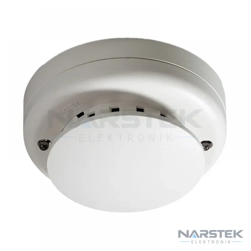
| Optical smoke detector | Check the alarm response using suitable smoke test equipment; inspect for contamination and physical damage. |
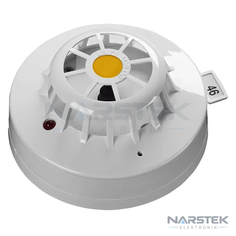
| Heat detector | Carry out a controlled heat test in accordance with the manufacturer’s procedure; verify the address and alarm status at the panel. |
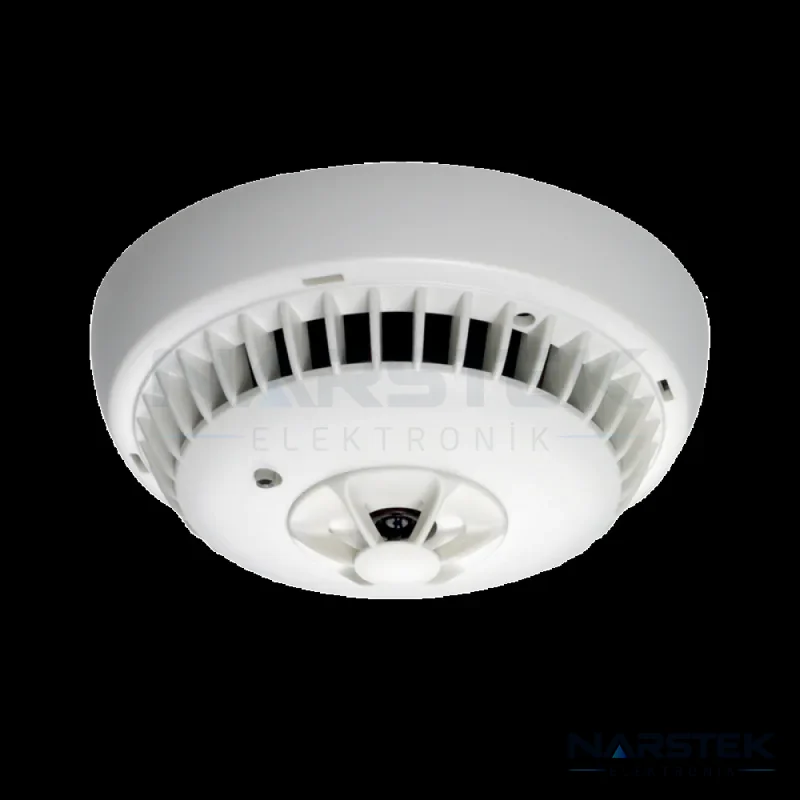
| Multisensor detector | Assess the optical and heat detection functions using a test method permitted for the device. |
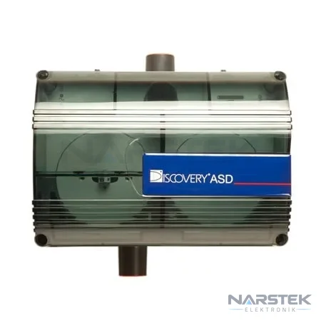
| Beam and aspirating detectors | For beam detectors, check alignment and the test method; for aspirating detectors, inspect the sampling unit and air sampling points in accordance with the manufacturer’s documentation. |
| Manual call point | Verify the alarm input using an authorised test key or the method specified by the manufacturer. |
Applying the same aerosol or heat source to every detector is not appropriate. In particular, follow the manufacturer’s testing instructions for beam, aspirating and multisensor devices. Test equipment must not contaminate or damage the device. If sounders and beacons are included in the system scenario, also check their operation and how they respond to panel commands.
Examples of different detection types include DP2061N optical smoke, 55000-400APO heat, PL 3300 OTI multisensor and 29650-081APO aspirating detectors. These products are associated with different systems and protocols; do not replace a product without checking its compatibility with the existing panel. For other options, see the detectors category.
Cause-and-effect scenario and test matrix
An alarm from a detector alone does not complete the maintenance test. Compare which sounders, beacons, door holders, fans and other controlled equipment should operate with the project’s cause-and-effect matrix. For each scenario, record the initiating device, the alarm information displayed at the panel and the expected outputs.
Plan tests with the building representative to minimise disruption to building use. If alarm transmission or connection to another system is involved, inform the relevant parties before testing and record any required change to test mode. After testing, remove any disablements, reset the panel and confirm that it has returned to normal monitoring.
What should a maintenance report include?
The report should not consist solely of the statement “the system is working”. The building manager should be able to see which devices were tested, which faults were found and what follow-up work is required. Any discrepancies with the project documentation or device list should also be clearly recorded.
- Maintenance date, building and panel details, and the team carrying out the inspection.
- Devices and addresses checked, test results and any non-operational devices.
- Devices with analogue values or contamination warnings, and the recommended action.
- Scope of the loop and isolator checks, faults found and measures taken.
- Cause-and-effect testing, event log review and the panel’s post-maintenance status.
- Outstanding faults, recommended corrective actions and any temporary restrictions the building representative needs to know about.
Batteries are also power supply components that need to be checked during maintenance. Fire alarm control panels generally use 12 V VRLA lead-acid batteries, which may be replaced approximately every 3-5 years in accordance with the manufacturer’s recommendations. The correct capacity is assessed against the required standby and alarm durations; the power supply is covered by TS EN 54-4. If batteries need replacing, record the capacity used and the replacement details in the report.
Article 84 of the Regulation makes the building owner and manager responsible for ensuring that emergency lighting, signage, and fire detection and alarm systems undergo the periodic inspections, tests and maintenance required by the relevant standards and the system. The article does not specify a single interval in days or months for all buildings; maintenance frequency is determined according to the standards and the requirements of the system. In the sector, at least two comprehensive maintenance visits per year, together with regular brief checks by the user, are common practice. This should not be understood as a mandatory frequency set by legislation. For maintenance planning, you can review the fire alarm system maintenance checklist and our service and maintenance services.
To request a maintenance quote from Narstek
Narstek Elektronik provides site surveys, design, installation, maintenance and fault repairs for fire detection and alarm systems, based in Istanbul. Support is also available across Türkiye for projects outside Istanbul and product supply. To help us assess your system, please share the panel make and model, building address, approximate number of devices, any existing drawings or device lists, and known faults.
If available, please also send the most recent maintenance report, any fault messages displayed on the panel, and details of any alterations carried out. This will help us assess in advance whether your request requires maintenance, fault response, or an update to the drawings or device list. You can use the site survey and quote form, call us on 0212 424 07 24, or message us on WhatsApp at 0540 001 07 24. E-mail: info@narstek.com. Address: Tevfikbey Mah. Halkalı Cad. No:112 Nazlı İş Merkezi Kat:3 Ofis No:64 Küçükçekmece / İstanbul.
Frequently asked questions
What checks are carried out first during addressable fire alarm maintenance?
First, the device list in the panel is compared with the project documentation and the devices on site. The panel faults, disabled points, address information, analogue values and event logs are then reviewed.
Is every detector tested in the same way in an addressable system?
No. Smoke, heat, multisensor, beam and aspirating detectors require different test methods. Equipment appropriate to the detector type and the manufacturer’s instructions must be used.
How often should a fire alarm system be maintained?
The regulations do not specify a single fixed interval in days or months; inspection and maintenance frequency is determined in accordance with the relevant standards and the system’s requirements. Comprehensive maintenance at least twice a year is common industry practice, but this should not be taken as a mandatory frequency specified by law.
What information should be included in the report when maintenance is complete?
The report should document the addresses and devices tested, the panel and loop status, contamination warnings, cause-and-effect tests, the event log review and any outstanding faults. It should also clearly state if the system has returned to normal monitoring status after maintenance.
Share the panel brand, number of devices and address, and we’ll get back to you about a site survey and quote.